|
|
|
|
Cooling towers ВГ-144
|
Cooling towers of ВГ-144 series
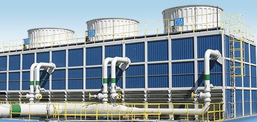
The cooling towers of ВГ series are designed for cooling the circulating water in the closed water circulating cycles with water consumption from 3000 to 30 000 m3/h and are specially designed for giant enterprises of metallurgical, petrochemical industry and thermal power plants and nuclear power plants.
The cooling towers of ВГ series are open counter-flow cooling towers and work on the principle of counter-flow of water and air flow. Air enters through the inlet windows, which are located at the bottom of the tower, goes through the irrigator towards the water flow and is discharged at high speed into the atmosphere.
Usually the cooling towers of ВГ series are interblocked in a single housing with the number of sections from 2 to 4. (According to regulatory requirements for companies in this industry sector with regards to compulsory equipment redundancy: “the number of pieces of equipment must be no less than 2 pcs”). As each section of the cooling tower has its fan installation and is able to work independently, sectioning by adding a backup section allows to provide redundancy for cooling equipment. Redundancy allows to perform regular preventive maintenance work without stopping of the entire processing equipment.
The index corresponding to the number of interlocked sections is indicated in the name of the cooling tower, when several sections are interblocked. The square of one section of cooling tower is also indicated in the name of the cooling tower. For example: 4ВГ-144 – 4-sectional fan cooling tower, section square of 144 m2 (section size 12х12 m, the overall size of the cooling tower 12х48 m).

Fig.1 Cooling tower ВГ-144
In the design of cooling towers of ВГ series, along with the metal works, which are usual for typical cooling towers, fiberglass reinforced plastic (FRP) is partially used, of which the elements most vulnerable to corrosion are made. To such elements belong: bridging of the cooling tower (due to the fact that that moist air containing aggressive substances rises), collector of water distribution system (is in direct contact with circulating water), covering of the cooling tower (is the boundary of contact of warm and moist air of the cooling tower with the environment, the temperature of which varies significantly throughout the year), the louver of the air inlet windows and the main staircase, pillars under for water catcher.
All load-bearing structures of cooling tower (framework, support structures for mechanical group and irrigator) are made of carbon steel with corrosion protection.
There are two options of corrosion protection of the cooling tower metal components.
The first of which is the transportation primer, at this the metal work is assembled using electric arc welding and after grinding of the welded joints the final paintwork is applied. The costs of both, the paintwork and work on its application are not included in the price of the cooling tower and should be made by the Customer.
More reliable anti-corrosion protection is hot galvanizing, which is performed in plant conditions. At this metal work of the cooling tower is assembled by bolted connections.
The constituent parts of the cooling tower (irrigator, water catcher, nozzles) are made of polymeric materials, which also eliminate corrosion.
Fixing elements (fasteners) for attachment of covering are made of galvanized steel.
Given combination of materials furthers simplification of the cooling tower design, as well as increase of reliability and service life at relatively low increase in cost associated with usage of FRP.
The assembly hatches for levels of irrigator and water distribution system are provided for ease of maintenance of the cooling tower of ВГ series, also FRP main staircase may be provided as an extra option of (Fig.2,3)
  
Fig. 2 Main staircase of the cooling tower of ВГ series Fig.3 Assembly hatch
In addition to de-icing device in the lower part of the cooling tower (hand-operated louvers, the mesh on the air inlet windows, preventing the penetration of ice into the inner space of the cooling tower), automatic speed reduction of the electromotor or shutdown of the fan installation electromotor, when the cooled water temperature is below the set value (control and monitor system of the cooling tower), is provided and also the option of actuation of fan installation in the “reverse” mode (to defrost the elements of the cooling tower) is given in block fan cooling towers manufactured by PJSC “Brotep EKO” in order to prevent freezing in the winter.

Fig.4 Regulated louvers on the air inlet windows
The cooling towers of ВГ series are installed on a prepared reinforced concrete pool with pylons (reinforced concrete pool with the pylons is not included in delivery set). The number of pylons corresponds with the number of the cooling tower sections. The pylons are designed for installation of fan installation.
 
Fig. 5 Reinforced concrete pool with the pylons for installation of cooling tower of ВГ series
Technical characteristics
|
Parameter name |
Measuring unit |
Name of cooling tower |
|
2ВГ-144 |
3ВГ-144 |
4ВГ-144 |
|
Operation conditions |
|
|
|
Performance range of the cooling tower on water |
m3/hour |
2000-4300 |
3000- 6400 |
4000-8600 |
|
Nominal performance range of the cooling tower on water |
m3/hour |
2900-3500 |
4300-5200 |
5800-6900 |
|
Maximum temperature of heated water |
0С |
Not more than 65 |
|
Droplet entrainment |
% |
0,007 |
|
Evaporation losses at Δt=100C and air temperature according to air dry bulb
28-30 0С |
% |
1,5 |
|
Pressure in water distribution system |
MCE |
4-5 |
|
Cooling tower construction |
|
Type of cooling tower |
|
Counter-flow exhaust |
|
Number of sections |
pcs. |
2 |
3 |
4 |
|
Length of cooling tower |
m |
24,0 |
36,0 |
48,0 |
|
Weight of cooling tower |
m |
12,0 |
12,0 |
12,0 |
|
Dimensions of section |
m |
12,0х12,0 |
|
Height of water inlet |
m |
5,755 |
|
Height of diffuser |
m |
2,1-3,5 |
|
Total height of cooling tower |
m |
10,3 - 11,7 |
|
Number of clamping shoulders of water inlet |
mm |
8pcs.х Ду300 |
12pcs.х Ду300 |
16pcs.х Ду300 |
|
Square of one section |
m2 |
144 |
|
Irrigation area |
m2 |
288 |
432 |
576 |
|
Fan installation |
|
Number of fans |
pcs. |
2 |
3 |
4 |
|
Type of installation |
|
Axial |
|
Type of drive |
|
Direct drive |
|
Rotation rate of electromotor |
rpm |
187,5 |
|
Rotation rate of fan |
rpm |
187,5 |
|
Fan diameter |
mm |
6990 |
|
Blades material |
|
polymeric amide |
|
Number of electromotor speeds |
|
1 |
|
Noise level on the distance of 10m |
dB |
< 80 |
|
Electromotor parameters |
V/HZ/F |
380/50/3 |
|
Nominal power of electromotor |
kW |
2х75 |
3х75 |
4х75 |
|
Electromotor protection |
|
IP55 |
Basic constituent parts of the cooling tower of ВГ series
|
Frame of the cooling tower |
|
 
|
|
The frame of the cooling towers of ВГ series is an assembled bearing structure made of carbon steel with corrosion protection (transport primer or hot galvanizing). The frame of the cooling towers of ВГ series is installed on a prepared reinforced concrete pool with pylon (reinforced concrete pool with the pylons is not included in delivery set). Fastening of the frame is made directly to concrete basin (pool).
Supporting elements for the covering and the water distribution system and water catcher are also made of carbon steel with corrosion protection, which is similar to one used for the frame.
The main staircase is provided for maintenance of fan installation. Also protective fence is provided along the perimeter of the cooling tower. Besides that technological hatches are provided for access to the irrigator and water distribution system.
The anti-icing system: air directing plates (louver) with manual mechanical operation are provided on the air inlet windows of the cooling tower. These plates regulate the amount of air that enters the cooling tower. The operation with closed air inlet windows is allowed in winter to prevent freezing of the irrigator. On the air inlet windows there is a protective grid made of steel protected against corrosion by hot galvanizing, which prevents the penetration of ice to inter irrigation space. Also there are measures on avoidance of icing in setting of the control and monitor system. The system automatically adjusts the fan rotation rate depending on the temperature of the cooled water and when it reaches a set minimum rate, below which the icing is possible, fan electromotor automatically turns off. When the temperature increases, fan installation is actuated respectively (details see section “control and monitor system of the cooling tower”).
All structural elements are designed in accordance with international norms and standards with regard to the requirements for wind loads and seismic loads. |
|
Covering, wind partitions, the bridging of the cooling tower |
|
 
|
|
The panels, as well as wind partitions, are made of fiberglass (fiberglass reinforced plastic, δ=2.0 mm) and are fastened to the steel frame with the usage of galvanized steel joints. Design eliminates air leak through thinness of covering.
The proposed material (fiberglass reinforced plastic) has high mechanical strength and wear resistance, is not vulnerable to corrosion. The temperature range, in which it is possible to use fiberglass reinforced plastic – from “-70” up to “+120”0C.
The covering made of fiberglass panels proved to be excellent in conditions of the environment with high humidity and chemical exposure (the used material is non-flammable, resistant to acids, alkalis, fats, oils, ultraviolet). |
|
Water catcher |
|

|
To effectively capture water droplets in the used airflow we offer to install cell water catcher BC-150. This design of water catcher furthers the efficient capture of water and reduces water loss with the entrainment up to 0.007% of the total water consumption for the cooling tower due to 3 time changing of the air flow direction. It also has excellent aerodynamic characteristics: reduces capacity requirements of the fan and provides additional contribution to increase of the cooling capacity of the cooling tower. The water trapper is made of PVC, which does not support combustion, is resistant to acids, alkalis, fats, oils, ultraviolet. |
|
Water distribution system |
|

|
|
The water distribution system of the cooling tower is a collector consisting of the supply and distribution pipes. The nozzles are evenly located on each distribution pipe. The water distribution system of one section of the cooling tower includes 4 feeding collectors Дy 300, to which distribution pipes are connected. To ensure reliable corrosion protection and long life of the water distribution system, we recommend to install the collector made of fiberglass.
Advantages of fiberglass water distribution system:
- the collector of the fiberglass reinforced plastic has a significantly longer life compared to metal one (the warranty period for fiberglass reinforced plastic pipes – 30 years, while the comparable figure for metal pipes is 5 years);
- collector made of fiberglass reinforced plastic does not require corrosion protection and subsequent maintenance work;
- high resistance to chemically active substances;
- fiberglass reinforced plastic does not support combustion;
- no “wandering” flows;
- the collector is supplied in unassembled from, which reduces transport costs;
- it is assembled by means of flange connections, which provides the possibility of its checkup and cleaning; |
|
- the coefficient of roughness of fiberglass pipes is much less than that of the ferrous metal pipes, in result, the flow capacity of fiberglass pipe is not reduced with time (the inner surface of the pipe is practically not blocked);
- lightness of fiberglass reinforced plastic pipes substantially reduces the complexity of installation, which consequently reduces the time and cost of the works;
- fiberglass pipes have good acoustic absorption, therefore, transmission of noise caused by flow of water through pipes is limited;
For even flow distribution and efficient aerodynamic mode, the spray nozzles of dynamic type with cup-shaped reflector are used. They are made from polypropylene.
These nozzles have a direct water output channel, which significantly reduces the risk of clogging with impurities, which are in the water. The design of the nozzle (the cup-shaped reflector) increases the time of contact of water with air in over irrigation space that will reflect well on the overall cooling efficiency of the cooling tower.
The design of the water distribution system of each section provides the complete discharge of water at the output after usage. |
|
Irrigator |
|
 
|
|
To ensure high cooling efficiency, the cooling tower will be equipped with a combined irrigator, consisting of corrugated PVC sheets of film irrigator and net blocks.
The film irrigator with cross-corrugated channels furthers improvement of water distribution by splitting the water flow. The water flow is splitted at least ten times as it passes over the surface of irrigator. The square of the heat-mass exchange of film irrigator under low specific load on the support structure significantly exceeds the same indicator of other types of irrigator.
Specially designed corrugating, designed microstructure and high standards of manufacture allow to achieve high thermal efficiency with minimal pressure loss.
Features and benefits of film irrigator made of PVC:
- improved distribution of water;
- high resistance to contamination;
- special additives for high resistance to UV radiation;
- high efficiency of heat dissipation;
- special edges for directing the water on both sides of the sheet;
- the irrigator is made of PVC material, which does not support combustion (in accordance with the Standard 136 of Cooling Technology Institute CTI).
The water distribution net blocks are installed on top of the film irrigator. This decision improves the water distribution in the irrigation space, accelerates the formation of a thin film of water and protects the irrigator from directional non sprayed water flow in case of failure of the nozzle. |
|
Fan installation |
|
 
|
|
Each section of the cooling tower equipped with fan installation ВГ-70, which consists of a diffuser, impeller and electromotor.
The diffuser of the fan installation is made of laminated fiberglass, has a stream-lined inlets, where there is a minimum clearance between the edges of the blades and the housing of the diffuser. The height of the diffuser is determined by calculation and can vary within 2.1 3.5 m. The diameter in the area of impeller rotation is 7050 or 8050 mm. The advanced systems of design analysis and application of digital production technologies ensure perfect circle in the area of impeller rotation. The multilayer structure of the diffuser has a specially designed system of stiffener plates; due to this it has light weight and high strength. A hatch is provided for access the fan.
The cooling towers of ВГ series are equipped with 3,4-or 5-blad impeller with diameter of 6990-8000 mm.
The blades of the impeller are made of epoxy resin reinforced with glass fibre (fibreglass), with corresponding values of of spin and cone ratio for for maximum airflow. All blades are manufactured with the same moment of the mass to allow replacement of individual blades without the need of re-balancing, i.e. each blade can be mounted individually. The fixing elements are made of stainless steel.
The fiberglass impellers have a considerable number of advantages in comparison with aluminum blades and, especially, with carbon steel:
- high corrosion resistance both chemical and mechanical;
- the possibility of forming a complex profile of the blade, which provides better performance;
- high class of dynamic balancing of impellers – 6.3 G;
- low specific gravity of the material;
- reduction of noise and vibration;
- reduction of starting currents of the electromotor;
- less time-consuming installation works;
- longer service life due to the use of corrosive resistant material.
For drive of the fan installation impellers, the electromotors of leading European manufacturers with optimally matched power in a sealed air-cooled design with special insulation for cooling towers are used.
The cooling towers of ВГ series are equipped with 75 or 90 kW electromotor of АСВО5К-75 (90)-32У1 brand.
The electromotors of АСВО5К brand are asynchronous with squirrel-cage motors, vertical ones are designed for gearless direct drive of axial fans. The single-speed motors brand АСВО5К are equipped with bearings, which make replenishment of the lubricant possible in the operation without disassembling the motor. The estimated durability of the bearings is not less than 70 000 hours. In the lower end shield of the motor there are plugs for condensate draining.
The motor start is direct and is performed at nominal circuit voltage as well as at the voltage reduced during start-up to 0.8 Unom.
Speed control is possible with ЧП in the range from 10 to 50 Hz
Degree of protection of housing and terminal box: IP55.
Class of insulation of stator windings: F.
Installation execution: IМ9631 (vertical, shaft up).
Cooling method: ІСА0141 - external air cooling by cooling tower fan.
Motors of АСВО5К brand are equipped with:
- vibration sensor;
- temperature sensors of the upper and lower bearings with a nominal static characteristic of the РТ -100, output signal 4-20 mA;
- temperature sensor of winding (posistor), the output signal is “dry contact”;
- anticondensation heating system (ТЭН - 2pcs.).
The use of electromotors of АСВО5К brand in set with frequency converter allows to operate these motors in a power range 40÷100%, allowing a more accurate selection of optimal power/speed of the electromotor depending on the required cooling capacity. |
|
Control and monitor system |
|

|
|
The control and monitor system with frequency-regulated drive is included in delivery set for possibility of automation of cooling tower operation. The analysis of work of similar motors with frequency converter showed that the maximum power consumption is observed in the most unfavourable for the operation of the cooling towers period of the year for several hours, when the air temperature according to air wet bulb reaches the maximum. The possibility of operation of the electromotor at any load of power operating range can significantly reduce overall power consumption.
The control and monitor system with frequency-regulated drive provides:
- manual and automatic control of the fan rotation rate depending on the temperature of the cooled water (significant energy saving);
- shutdown of the electromotors, when the temperature of the cooled water drops below 10-15 º C to prevent freezing in winter (setting of the cooled water temperature is set based on the climatic conditions of the installation area of the cooling tower);- the actuation of the fans in reverse for de-icing;
- safety shutdown in case one of the controlled parameters (temperature of bearings or windings of electromotor, vibration, accidents in the electricity grid)comes out of a permissible range;
- automatic startup of each motor after restoring of the monitored parameters;
- start up of the electromotor in a mode, which is moderate for him and starting equipment (increase of service life);
- monitoring of status alarms and control of the cooling tower fan in manual and automatic mode from local control means as well as from the controller of the control system (the possibility of connection of input and output channels);
- display information to the upper level through standard protocols and ranges of signals;
- braking of spontaneous rotation of the impeller.
The operation of control and monitor system is based on the performance of the following instrumentation and control equipment:
- vibration sensors (4-20 mA output signal),
- sensors of electromotor winding temperature (PTC thermistor),
- sensors of electromotor bearing temperature (РТ100 with normalizing transducer, 4-20mA signal),
- sensor of cooled water temperature (50M with normalizing transducer into 4-20mA signal), shows them on the display of the visualization panel of the controller located in the control cabinet. Also the display shows readings of:
- sensor of heated water temperature
- rotation rate of fan installation.
- current consumption of each electromotormotor
Local operating post of manual control is provided. |
|
Maintenance of the cooling tower |
|
|
|
On one side of the cooling tower there is a staircase, made of fiberglass, with height from water level to the level of the deck. The fiberglass fencing is installed along the perimeter of the roof.
The technical hatch for accesses to the level of the irrigator and water distribution system is provided in cooling towers of ВГ series.
For maintenance of fan installations there is a special area, which is mounted above the level of water catcher. |
|
 |
|
|